GATE VALVE HV
A new Gate Valve is developed in VSE VacuumTechnology. It contains significant new ideas which allows a full product range, excellent features and a great cost effectiveness.
The name of this productline:
![]()
![]()
These Gate Valves are available in:
• sizes 65, 80, 100, 150, 200, 250, 320, 400 and more
• flange standards CF, ISO, ASA, JIS
• handoperated with lever, handoperated with handwheel, pneumatic actuation and motor driven
• in HV version (with rotary feedthrough) or in UHV (with metal bellows and metal gaskets)
• with slide bearings (PTFE-slidebearings) for dirty environments.
HIGHLIGHTS
This new Gate Valve ensures excellent features: |
Smooth, vibration-free operation for the entire open/close cycle. |
 |
No springs in the mechanism, track-guided throughout the whole stroke. |
 |
Very low particle generation and insensitive against dust and dirt from outside the valve. |
 |
Locked in open and in closed position. |
| Insensitive in pressure difference: Nothing can hang-out, no damage if it opens against differential pressure. | |
| Long service intervals: 200,000 cycles in HV; 50,000 cycles in UHV version. | |
 |
All sizes: 63, 80, 100, 150, 200, 250, 320, 400. All flange standards, all actuators: handlever, handwheel, pneumatic, steppermotor. |
The mechanism. The valve and its mechanism is designed entirely in stainless steel and is based on a guided motion without the use of springs. The operating principle allows to operate the valve against any differential pressure from either side without damage. It depends on the level of differential pressure and its direction, that the valve might not be able to open, but it will stay without any damage.
Dirty environment: For any dirty process we offer a modified mechanism: In replacement of ballbearings in stainless steel we use solid rolls in stainless steel with slide bearings (SKF). These bearings are proven in use brillantly.
The housing is welded and it is designed to provide easy access to the inner mechanism for maintenance purposes. The mechanism can be completely removed from the housing.
Seals. The valve plate is tightened by a Viton O-ring, available off-the-shelf.
Seals HV. The HV valve uses a Viton O-ring as rotary feedthrough which is tested for more than 500,000 cycles. The gasket for the bonnet flange on the housing is a Viton O-ring too.
Seals UHV. The UHV valve uses a metal bellows as feedthrough which is tested for more than 100,000 cycles. The gasket for the bonnet flange is a reusable metal seal as well as the gasket for the bellows feedthrough.
Flanges. This GATE Valve is available with all common flange standards like CF, ISO, ASA, JIS. Additional any customized flange system is possible. Additional ports for pumping, venting or gauging are available.
Actuators. This GATE Valve is available in both versions HV and UHV in the following actuations:
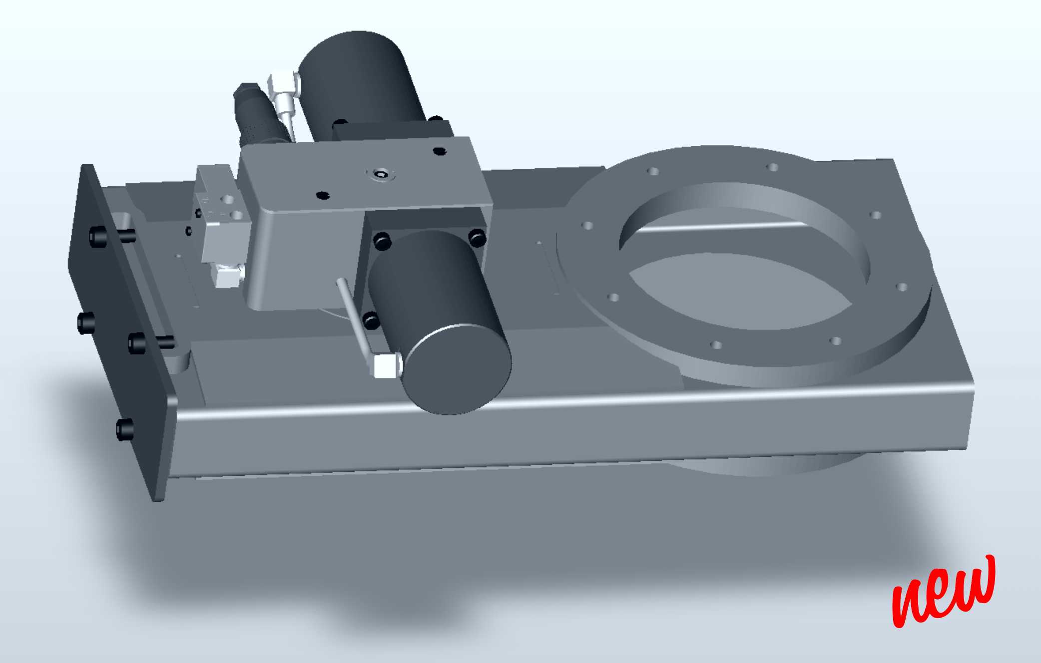
HOW IT WORKS
This is the inner mechanics:
A swivel arm turns for 180° and moves the mechanism from open to closed position. Two rollers perform the move of the valve plate in the Z-axis. All this run without any sliding friction, rolling only. The moving partners for this Z-axis are thin sheet in stainless steel with open distance to each other which makes this mechanism very insensitive against any dust and dirt coming from the customer's installation.
Most of the parts are made in lasercutted stainless steel. This allows to equip the valve with a great principle of actuation, but keep the prices inexpensive.
The mechanism is track-guided over the whole stroke from full open to full closed. This principle is patented in the most important industrial countries. Before we have started the new GATE Valve we have produced and tested this principle in many different sizes and tested for 1 million cycles (HV version) and 200,000 cycles (UHV version).
TECHNICAL DATA
 |
|
| Pressure range: | 1 . 10-9 mbar to 1,2 bar |
| Leakrate: | |
| Housing | < 1 . 10-9 mbar ls-1 |
| Valve seat | < 1 . 10-9 mbar ls-1 |
| Service interval | 200,000 cycles |
| Temperatures: | |
| Valve | 250°C open, 200°C closed |
| Actuator | 200°C |
| Solenoid valve | 80°C |
| Materials: | |
| Housing | 304 |
| Mechanism | 304, 321 |
| Actuator | 304, aluminium |
| Gaskets: | |
| Valve seat | Viton |
| Static gaskets | Viton |
| Actuator | Viton |
| Mounting orientation | any |
| Maximum differencial pressure at opening | 1,1 bar from either side |
ND
|
63 |
80 |
100 |
150 |
200 |
250 |
320 |
400 |
|
| Opening possible against valve plate*) | p (mbar) | 1000 |
600 |
300 |
250 |
200 |
150 |
100 |
100 |
| Opening possible with valve plate | p (mbar) | 1000 |
1000 |
1000 |
1000 |
1000 |
1000 |
1000 |
1000 |
| Conductance under HV | C (l/s) | 600 |
900 |
1700 |
5100 |
12000 |
22000 |
33000 |
50000 |
| Weight handoperated valve | kg | 8 |
10 |
10,5 |
26 |
32 |
47 |
74 |
110 |
| Weight pneumatically operated valve | kg | 9 |
11 |
11,5 |
28 |
34 |
50 |
77 |
115 |
| Closing- and opening time | s | 1 |
1 |
1,5 |
2 |
2,5 |
3 |
4 |
5 |
| Handwheel spindle turns | n | 17,5 |
17,5 |
17,5 |
12,5 |
18 |
26 |
26 |
34 |
| Handlever turns | 180° |
| Pneumatically operated valve:: | |
| Compressed air supply | 4 - 8 bar overpressure |
| Reaction to power failure | Valve closes and remains tight |
| Reaction to compressed air failure | Status remains: fully open or fully closed |
| Supply voltage of solenoid valve | Standard 24VDC |
| Power consumption of solenoid valve | 2,5 W |
| Contact rating of position indicator switches | 2 A (250VAC/24VDC) |
*) Valve opens with this differential pressure. If the differential pressure is higher, the valve don't open but no damage occurs.
Outline dimensions of the Gate Valve HV:
ND |
63 |
80 |
100 |
150 |
200 |
250 |
320 |
400 |
||||
A |
70 |
70 |
70 |
80 |
80 |
100 |
120 |
150 |
||||
B
|
CF |
113.5 |
117.5 |
152 |
202.5 |
253.2 |
||||||
ISO |
136 |
145 |
176 |
225 |
288 |
355 |
425 |
510 |
||||
ASA |
136 |
176 |
225 |
288 |
335 |
425 |
597 |
|||||
JIS |
136 |
176 |
225 |
288 |
350 |
425 |
510 |
|||||
C
|
CF |
8 x M8
ø 92.1 |
10 x M8 ø 102.4 |
16 x M8 ø 130.3 |
20 x M8 ø 181 |
24 x M8 ø 231.8 |
||||||
ISO |
4 x M8 ø 110 |
8 x M8 ø 125 |
8 x M8 ø 145 |
8 x M10 ø 200 |
12 x M10 ø 260 |
12 x M10 ø 310 |
12 x M12 ø 395 |
16 x M12 ø 480 |
||||
ASA |
4 x 3/8" 16UNC ø 120.7 |
4 x 3/8" 16UNC ø 152.4 |
8 x 3/8" 16UNC ø 190.5 |
8 x 3/4" 10UNC ø 241.3 |
8 x 3/4" 10UNC ø298.5 |
12 x 3/4" 10UNC ø362 |
16 x 1" 8UNC ø 539.8 |
|||||
JIS |
4 x M10 ø 120 |
8 x M10 ø160 |
8 x M10 ø 210 |
8 x M12 ø 270 |
12 x M12 ø 320 |
12 x M12 ø 370 |
12 x M16 ø 480 |
|||||
D |
142 |
154 |
170 |
234 |
316 |
376 |
450 |
552 |
||||
E |
71 |
77 |
85 |
117 |
158 |
188 |
225 |
276 |
||||
F |
132 |
150 |
165 |
230 |
332 |
376 |
480 |
560 |
||||
G |
222 |
249 |
275 |
378 |
525 |
581 |
741 |
885 |
||||
H |
230 |
230 |
250 |
300 |
388 |
390 |
528 |
528 |
||||
J |
96 |
96 |
98 |
112 |
134 |
153 |
164 |
172 |
||||
K |
114 |
114 |
114 |
144 |
200 |
220 |
305 |
305 |
||||
L |
84 |
84 |
85 |
98 |
119 |
133 |
146 |
154 |
||||
|
||||||||||||
Modifications reserved. |
||||||||||||
e-mail: office@vseworld.com
S